Flow control of liquid rocket engines
- Jun 14, 2017
- 3 min read
Two pieces of information are needed to determine the specific impulse (Isp) of a liquid rocket engine - thrust of the engine and the total propellant flow rate. The Isp is calculate by dividing the thrust by the total flow rate:

where: F = thrust (lbf)
W = total flow rate (lbm/sec)
Thrust is usually fairly straight forward to measure by using a load cell. The flow rate is more difficult to measure directly, however, because it typically requires the use of turbine type flowmeters and specialized instrumentation. If the propellant is a cryogenic liquid like LOX, the equipment becomes even more complicated.
A simple way around this is by use of a cavitating venturi as shown in Figure 1. The cavitating venturi is a very useful device for controlling and measuring the flow of propellants in a liquid rocket engine. They can also be useful for inhibiting feed system oscillations by decoupling the engine from the feed system upstream of the venturi. When installed in the propellant line between the tank and the engine, the cavitating venturi will give an accurate, steady flow rate based on the tank pressure and propellant temperature. As its name implies, a cavitating venturi is a venturi shaped flow passage that operates at flow rates high enough to ensure that the propellant is cavitating at the throat, which is the point of smalles flow area. The throat is where the fluid velocity is highest, and therefore, by Bernoulli's principle, the pressure is the lowest. If the velocity is high enough, the pressure at the throat will be below the vapor pressure of the fluid, causing vapor bubbles to form, a phenomenon also known as cavitation.

The reason cavitation is desired is because the vapor pressure of the fluid now becomes the downstream pressure that the cavitating venturi "sees". When the venturi is cavitating, the outlet pressure is the vapor pressure of the liquid, or Pv. The flow rate through the venturi is defined as:
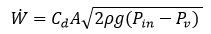
where: Cd = discharge coefficient
A = throat area
rho = density of propellant
g = gravitational constant
If the temperature and pressure of the propellant are known at the inlet to the venturi (tank conditions), then the density and vapor pressure of the fluid can also be determined.The CdA of the venturi can be measured by water flow calibrations, so all of the information that is needed to calculate the propellant flow rate is known.
To ensure that the venturi remains "in cavitation", the outlet pressure must stay below the recovery pressure of the venturi. The recovery pressure is the amount of pressure recovered by converting the liquid velocity to pressure in the shallow angle diffuser just downstream of the throat. A typical recovery value for a well made venturi is 80 and 85%. This means that the outlet pressure must be less than 80 to 85% of the inlet pressure for the venturi to be in cavitation. For example, if the inlet pressure (tank pressure) for a venturi is 1000 psia and the venturi has a recovery of 80%, then the inlet pressure to the engine must be less than 800 psia to ensure that the venturi is in cavitation. If the inlet pressure to the engine is only 400 psia, that's fine, the venturi will still provide the same flow rate as it would if the inlet pressure was 800 psia. That's the beauty of a cavitating venturi, the flow rate is constant no matter how the downstream pressure varies, as long as it does not rise above the recovery pressure of the cavitating venturi.


Comments